Major Components of a Gate Valve: An Overview. Let's zoom in a little closer to our friend, the gate valve. When you look at a gate valve diagram or a gate valve parts diagram, you can see the major components that make up this powerhouse: the body, the bonnet, the stem, the gate or disc, and the seat rings.. Gate valves control water flow with a brass wedge. Water ball valve. use a stainless steel ball to control water flow. There are three basic valve styles, making this a classic case of good, better and best (described in order as follows). All three can be used for water, oil or airflow control if the casting has 'WOG' stamped on it.
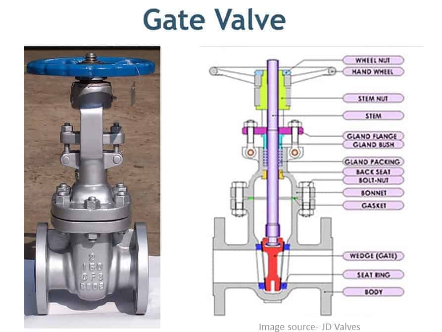
Different Types of Valves used in Piping A Complete Guide of Pipe Valves
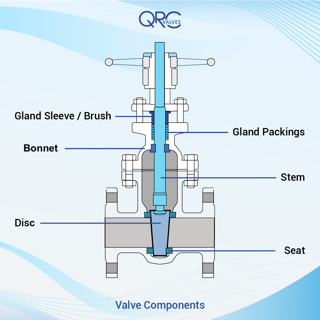
Gate Valve Components QRC Valves
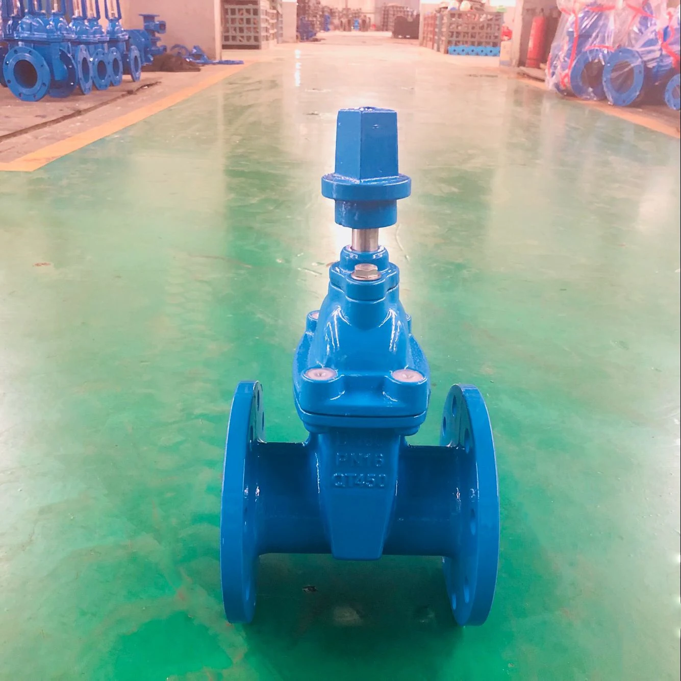
Dn 80 3 Inch Gate Valve Resilient Seat Ductile Cast Iron Gate Valve Square Nut Operation

GATE VALVE WORKING PRINCIPLE Mechanical Engineering Professionals
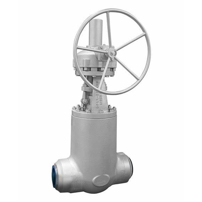
Parallel Single Disc Gate Valve DSNY ValveChina Professional Valve Factory
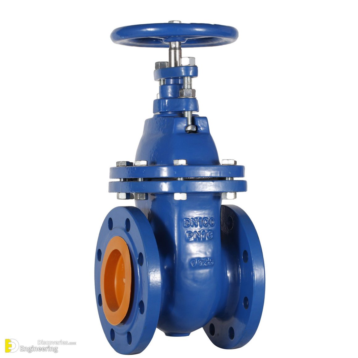
Types Of Gate Valve And Parts Engineering Discoveries

gate valve data sheet pdf Gate valve valves
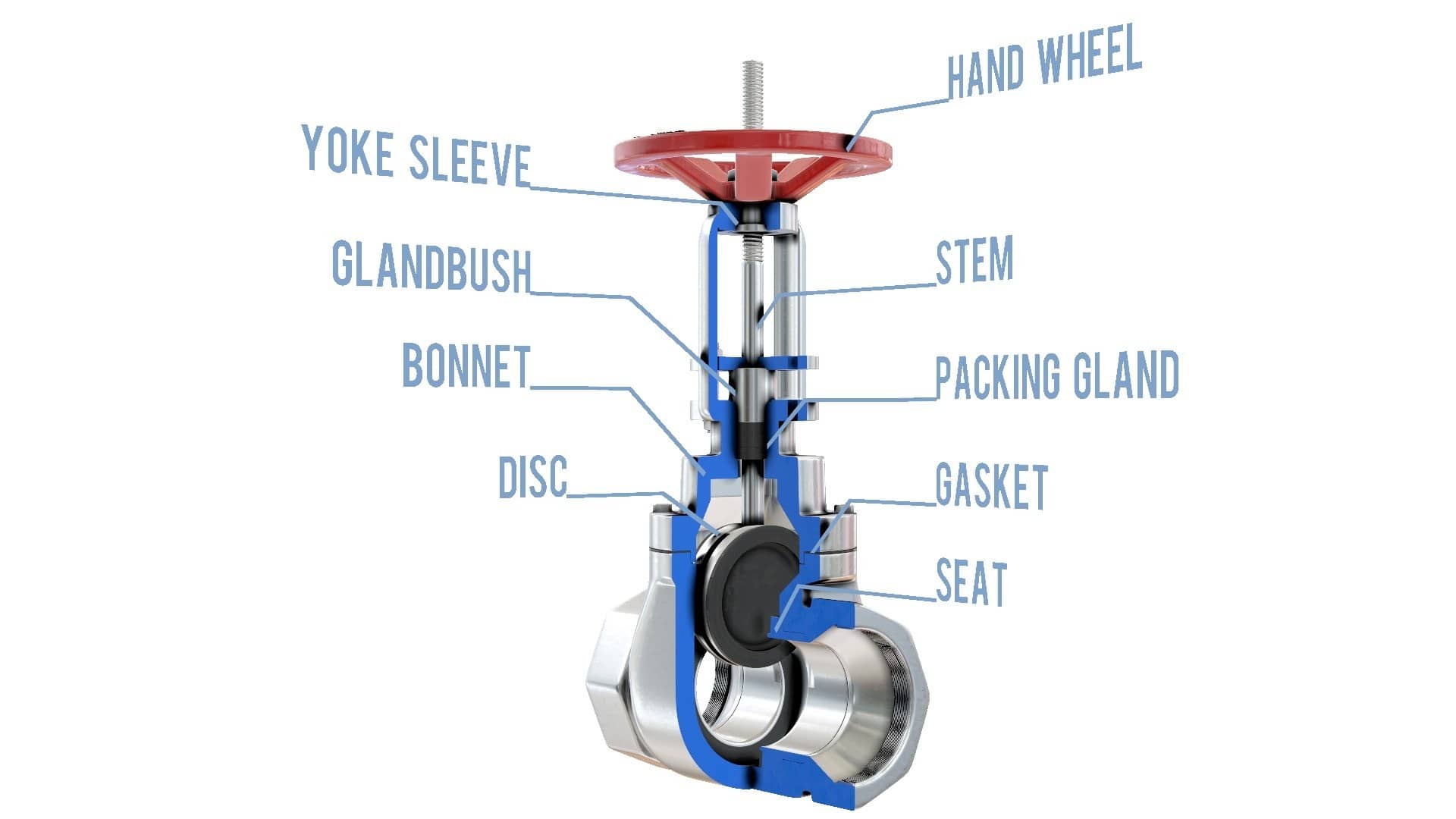
Gate Valve (Sluice Valve) Explained saVRee

Pin on Mechanical engineering
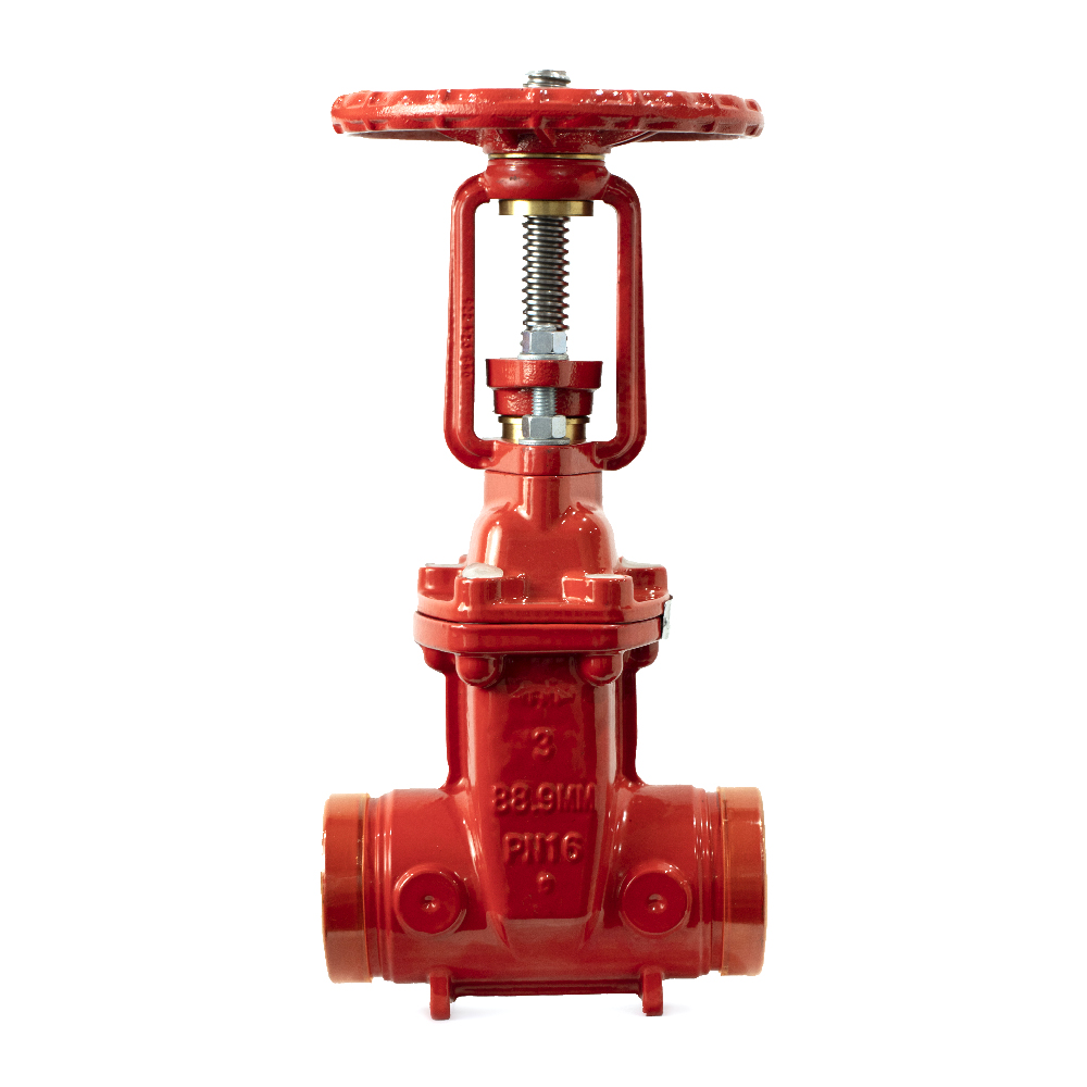
OS & Y Valve R/G *Gate Valve* Direct Fire Supplies
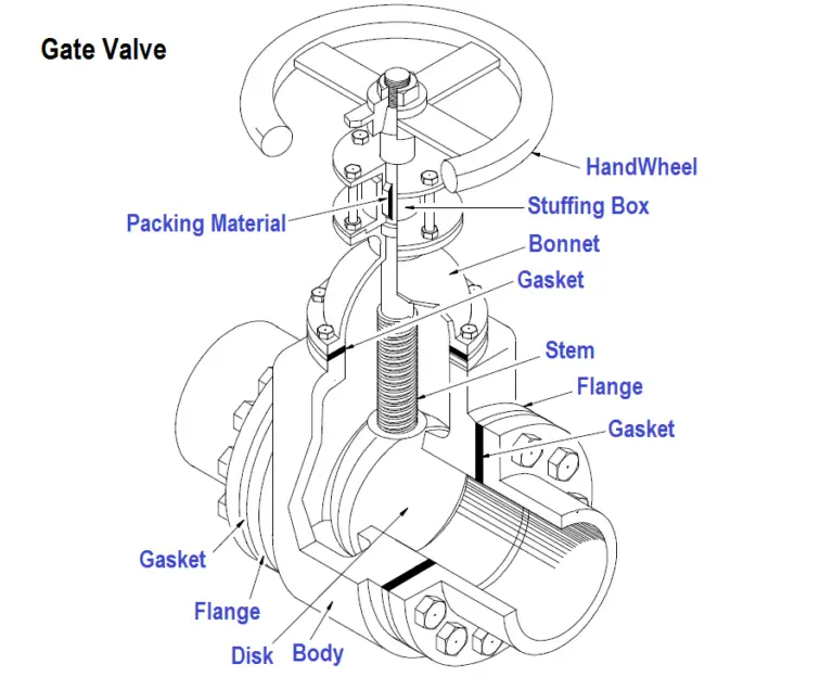
What is Gate Valve ? Gate Valve Parts Disadvantages of Gate Valve

15 Inches Square or Rectangular Motorized Slide Gate Valve with Electric Multiturn Actuators for
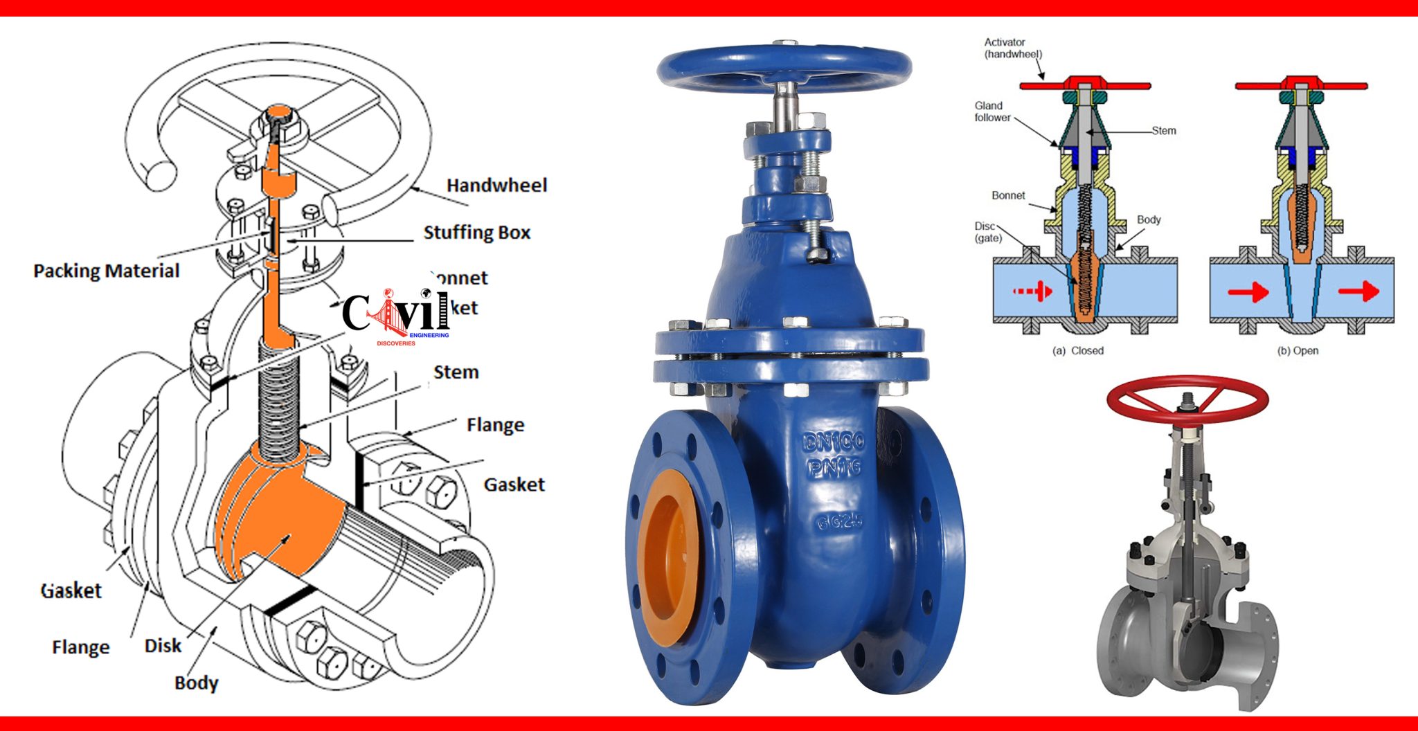
Types Of Gate Valve And Parts Engineering Discoveries

Gate Valves Types of Gate Valves (Plus Detailed Pictures)
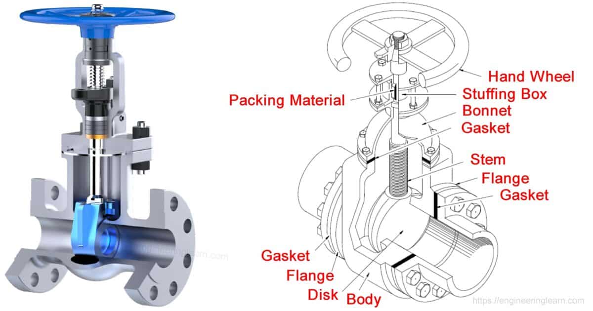
Gate Valve Types and Parts Engineering Learn
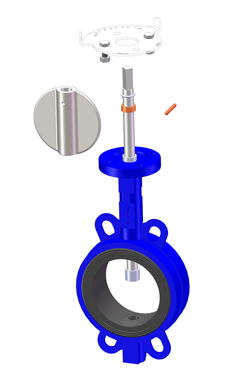
Gate valve butterfly valve check valve structure analysis diagram, exploded diagram TFW VALVE

Valves SK
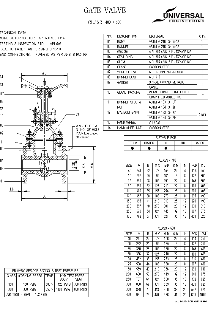
Universal Valve

gate valve diagram with parts Gate instrumentationtools disadvantages

Gate Valve Schematic
A gate valve is a linear motion valve used to start or stop fluid flow; however, it does not regulate or throttle flow. The name gate is derived from the appearance of the disk in the flow stream. Figure 4 illustrates a gate valve. The disk of a gate valve is completely removed from the flow stream when the valve is fully open.. A gate valve diagram illustrates the internal components and operation of a gate valve. The diagram typically shows the valve body, bonnet, gate, seat, stem, and handwheel. As the handwheel is turned, the stem moves up or down, causing the gate to open or close. The gate valve is used to control the flow of fluids in a pipeline and is often.