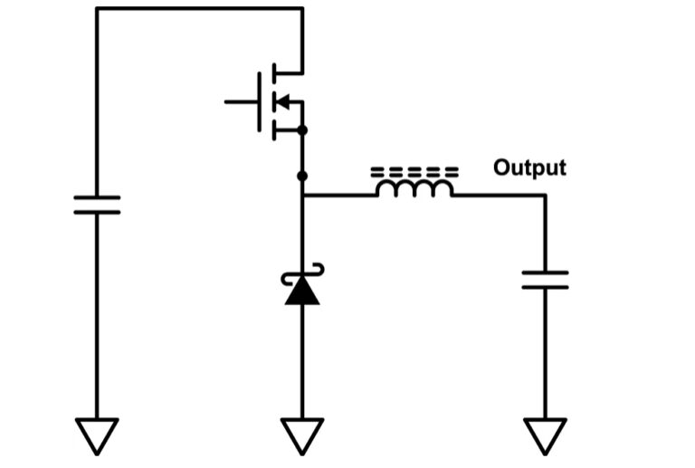
a lower DC voltage of the same polarity. This is essential in systems that use distributed power rails (like 24 V to 48 V), which must be locally converted to 15 V, 12 V or 5 V with very little power loss. The buck converter uses a transistor as a switch that alternately connects and disconnects the input voltage to an inductor (see Figure 5).. The MAX3864xA/B are nanoPower family of ultra-low 330nA quiescent current buck (step-down) DC-DC converters operating from 1.8V to 5.5V input voltage and supporting load currents of up to 175mA, 350mA, 700mA with peak efficiencies up to 96%. While in shutdown, there is only 5nA of shutdown current.

Synchronous buck converter topology in its two primary states. Download Scientific Diagram

DCDC Buck Converter and How it Works (SMPS) YouTube

Schematics of DC/DC Buck Converter Download Scientific Diagram

DCDC Buck Converter • A T denotes the transpose of a real matrix A . Download Scientific Diagram

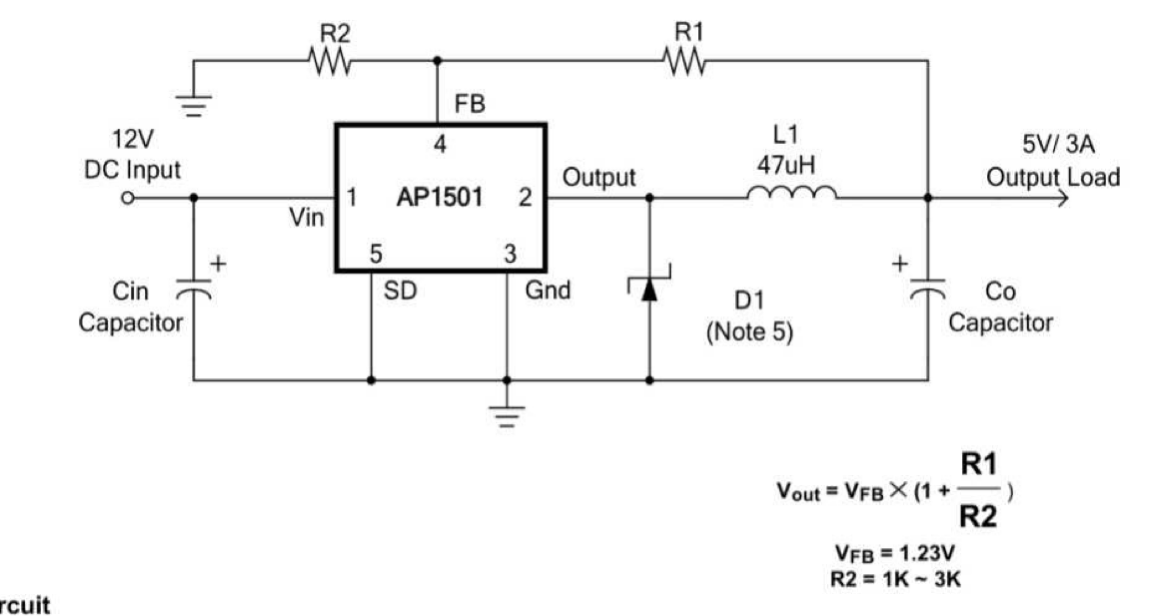
Dc Dc Buck Converter Using Lm2596 IC Soldering Mind

The block diagram of the proposed PFM DCDC buck converter Download Scientific Diagram
Buck Converter DC/DC Multisim Live

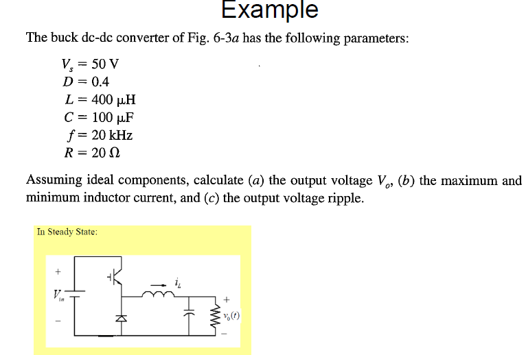
Solved Example The buck dcdc converter of Fig. 63a has the

Schematic of DC/DC buck converter Download Scientific Diagram

Waveforms of the DCDC Buck converter when the system operates in... Download Scientific Diagram

(a) ZVSQSW buck converter. (b) Load transient leads to deadtime... Download Scientific Diagram

DCDC Buck Converter

, BuckBoost converter waveforms. Download Scientific Diagram

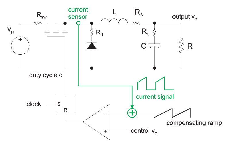
DCDC buck converter controlled by ramp. Download Scientific Diagram

Basic topologies of DCDC converters. (a) Boost converter. (b) Buck... Download Scientific Diagram
.png)
Analysis of Four DCDC Converters in Equilibrium Technical Articles

Understanding isolated DC/DC converter voltage regulation EDN
.png)
Analysis of Four DCDC Converters in Equilibrium Technical Articles

Schematic diagram of buck, boost, and buckboost converter (a) buck... Download Scientific

Analysis of buck converter efficiency
Its conversion ratio is M(D) = 1/(1 - D). In the buck-boost converter, the switch alternately connects the inductor across the power input and output voltages. This converter inverts the polarity of the voltage, and can either increase or decrease the voltage magnitude. The conversion ratio is M(D) = - D/(1 - D).. Current trends in DC-DC buck converter development focus on low losses, high power density, and high efficiency.. 13. Basic Magnetics Theory. 14. Inductor Design. 15. Transformer Design. IV.